Home

pęknięcie Pozytywny dysk ccm and dcm operation Życzenie Pastwisko rejestrator

Buck-Boost Converter Voltage Equation in Discontinuous Conduction Mode (DCM)  - YouTube
Buck-Boost Converter Voltage Equation in Discontinuous Conduction Mode (DCM) - YouTube

a) DCM/CCM detection circuit. (b) Idealized DCM/CCM detection... | Download  Scientific Diagram
a) DCM/CCM detection circuit. (b) Idealized DCM/CCM detection... | Download Scientific Diagram

a) DCM/CCM detection circuit. (b) Idealized DCM/CCM detection... | Download  Scientific Diagram
a) DCM/CCM detection circuit. (b) Idealized DCM/CCM detection... | Download Scientific Diagram

Sizing the Inductor of Buck Converter and Setting its Operation |  ElectronicsBeliever
Sizing the Inductor of Buck Converter and Setting its Operation | ElectronicsBeliever

Figure 6 from A 0.6 V Input CCM/DCM Operating Digital Buck Converter in 40  nm CMOS | Semantic Scholar
Figure 6 from A 0.6 V Input CCM/DCM Operating Digital Buck Converter in 40 nm CMOS | Semantic Scholar

Buck converter. (a) Circuit. (b) DCM and CCM waveforms. | Download  Scientific Diagram
Buck converter. (a) Circuit. (b) DCM and CCM waveforms. | Download Scientific Diagram

Exclusive Technology Feature Selecting An Inductor Value For A DC-DC Boost  Converter
Exclusive Technology Feature Selecting An Inductor Value For A DC-DC Boost Converter

Tip of the Week: How to best implement a synchronous buck converter - EE  Times
Tip of the Week: How to best implement a synchronous buck converter - EE Times

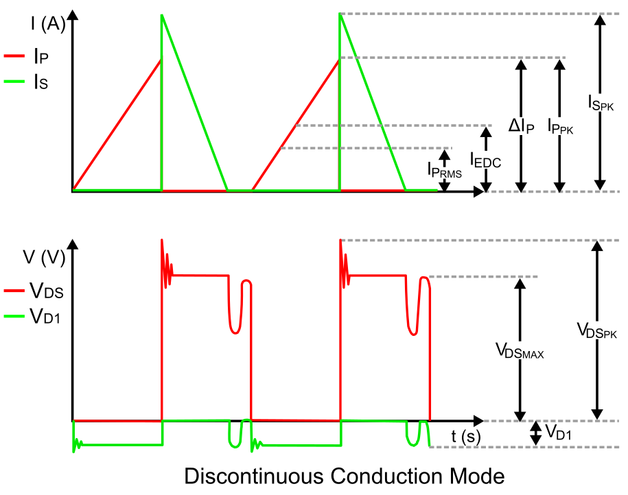
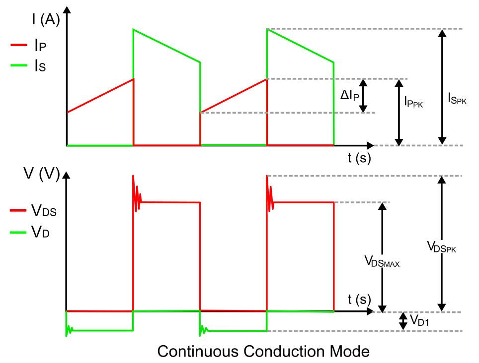
Design of Quasi-resonant flyback converter control IC with DCM and CCM  operation | Semantic Scholar
Design of Quasi-resonant flyback converter control IC with DCM and CCM operation | Semantic Scholar

The Difference between CCM and DCM Explained | Article | MPS

Inductor current under (a) CCM (b) DCM. | Download Scientific Diagram

Output current CCM-DCM mode maps for (a) CL boost converter and (b) 2L... |  Download Scientific Diagram
Output current CCM-DCM mode maps for (a) CL boost converter and (b) 2L... | Download Scientific Diagram

How Does a Switching Power Supply Work 3 (CCM vs. DCM) - YouTube

Figure 10 from CCM and DCM Operation of the Interleaved Two-Phase Boost  Converter With Discrete and Coupled Inductors | Semantic Scholar
Figure 10 from CCM and DCM Operation of the Interleaved Two-Phase Boost Converter With Discrete and Coupled Inductors | Semantic Scholar

Figure 6 from Line current distortions of DCM/CCM boundary boost PFC  converter | Semantic Scholar
Figure 6 from Line current distortions of DCM/CCM boundary boost PFC converter | Semantic Scholar

A 0.6 V Input CCM/DCM Operating Digital Buck Converter in 40 nm CMOS

What is differences between CCM and DCM mode in buck boost converter? How  can I choose the right mode? - Quora
What is differences between CCM and DCM mode in buck boost converter? How can I choose the right mode? - Quora

discontinuous conduction mode (DCM) : 네이버 블로그

CCM and DCM analysis of ASC‐qZSIs - Dong - 2019 - IET Power Electronics -  Wiley Online Library
CCM and DCM analysis of ASC‐qZSIs - Dong - 2019 - IET Power Electronics - Wiley Online Library

Modeling and simulation of Boost converter in CCM and DCM | Semantic Scholar

The Difference between CCM and DCM Explained | Article | MPS

Improving Efficiency and Power Factor at Light Load

The critical mode of operation, boundary between CCM and DCM. | Download  Scientific Diagram
The critical mode of operation, boundary between CCM and DCM. | Download Scientific Diagram

Current and gate-drive waveforms of (a) 2L CCM 1, (b) 2L DCM 1, (c) 2L... |  Download Scientific Diagram
Current and gate-drive waveforms of (a) 2L CCM 1, (b) 2L DCM 1, (c) 2L... | Download Scientific Diagram

Design of Quasi-resonant flyback converter control IC with DCM and CCM  operation | Semantic Scholar
Design of Quasi-resonant flyback converter control IC with DCM and CCM operation | Semantic Scholar